(Copied over from FB for posterity.)
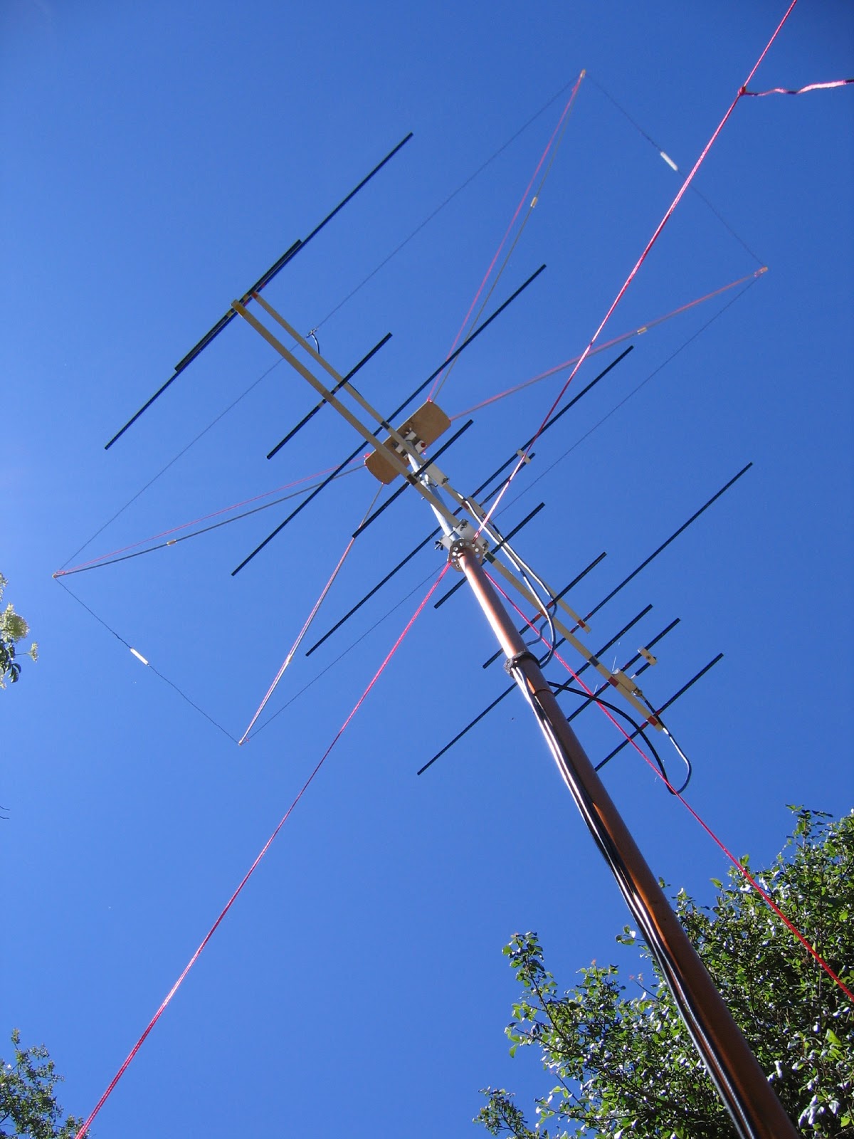
These are the VHF/UHF antennas that I carry when backpacking to the mountaintop for QRP contest operating.
From the top of the stack, a stressed Moxon for 50 Mhz, and two Arrow style yagis for 144 Mhz (4 elements), and 432 Mhz (8 elements).
The mast is a Kelty extendable tarp pole, which extends to 99" (8'3"). It is 1" (25mm) diameter, except for the lower section, which is slightly larger to telescope over the 1" section. I use it upside down, with an additional two 24" sections of 1" tubing above the guy ring to mount the antennas. The top of the mast is at ~12'.
Except for the Kelty mast, all of the components in this stack are homebrew.
This Moxon is made from 24awg (19x36) pvc hookup wire.
The insulators between the legs are made from pieces of a large nylon ty-wrap.
The center insulator is a small piece of 1/8" plexiglass.
The feedline is rg-58, with a nylon "snail" ty-wrapped to it, which is attached to the top of the plywood plate with a machine screw.
The center support is a piece of 1/2" birch plywood, with brass screw inserts to mount the mounting bracket, and the feedline strain relief.
The rods are 3/16" fiberglass rods from Tap Plastics, cut into 24" segments, and coupled with #10 nylon standoffs drilled out to 3/16", and epoxied to one segment.
The wire loop is attached to the rods using #10 standoffs, drilled
halfway to 3/16", and drilled cross-ways for the wire, with a #10 nylon
screw trimmed to length to hold the wire in place.
The rods tend to
flop around, so some braided nylon "mason twine" is used to provide some
diagonal tension to keep the loop square.
The mounting bracket is a piece of 3/4"x3/4" aluminum angle, with a piece of 1/2" aluminum channel, notched out to fit the mast contour, with a pair of #8 stainless machine screws and wing nuts.
The yagi's are custom Arrow type designs, using aluminum arrow shafts as the elements, with 8-32 threaded inserts and 8-32 threaded rod to attach them through the boom.
The designs were done in NEC4, for target frequencies of 144.250, and 432.150.
The boom is 1/2" square aluminum tubing left over from some wall mounted wire shelving. The boom length is 42", and once I cut them, and add the splices (3/8" aluminum rod inside the tubing), will break down to less than 24" per segment. The mounts are similar to the Moxon, with a strip of aluminum, and a pair of screws to hold the boom to the aluminum angle.
The gamma matches are made from 1/2" square bar stock, drilled to accept a chassis mount BNC at one end, using some teflon RG-6 with the shield removed as the internal element. The internal element passes through the block, and out the side into the stub, which forms the capacitor. The shorting bar is a sandwich of two pieces of 1/2"x1/4" aluminum bar stock. The design was a WAG (Wild A** Guess), but after some fiddling, tuned up nicely with the aid of a HP network analyser.
They guy ring is a piece of 1/16" aluminum plate, punched with a 1" chassis punch, trimmed into a octogon with tin snips, drilled with holes every 3/8", and the edges sanded. It fits over the 1" mast extension, at the top of the Kelty pole (which is really the extendable bottom section, with is larger than rest of the mast, which is 1"). The guy lines are braided mason twine.
The mast extension segments are 1" aluminum tubing, with a coupler made from a 3" piece of a scrap aluminum handlebar (which happens to fit perfectly inside the 1" tubing), drilled and tapped for 4-40 machine screws to hold the pieces in alignment. Eventually I will drill and tap the rest of the mast to allow the whole mast to lock together in alignment over the entire length.
A 1" internally threaded PVC plumbing fitting with threads filed down to form a friction fit keeps the mast extension from slipping down, but will be removed when I get around to drilling and tapping the mast to lock it together all the way up, to allow it to be rotated from the bottom.
The top of a plastic food container is drilled to accept the spike at the bottom (top) of the Kelty pole, and is marked with compass headings in 15 degree increments. (not visible in these photos). This allows the mast to be turned from ground level, from under a tarp, or inside a tent .
The Kelty pole I use is this one: http://www.kelty.com/p-134-adjustable-pole.aspx
Showing posts with label amateur radio. Show all posts
Tuesday, July 2, 2013
Sunday, December 25, 2011
Thoughts on improvements to the FT-817
There are periodic discussions on the various forums and mailing lists about the FT-817, and improvements that people would like to see in a successor radio.
This would apply to Yaesu, as well as any other manufacturers (Icom/Kenwood/Elecraft/Alinco/Ten-Tec) if they were to come out with a competing radio.
Commonly listed features include:
higher power (10w is the usual figure)
built-in auto-tuner (similar to the Elecraft T-1)
different antenna connectors
latching antenna relay
more robust power connector
built-in digital modes
USB interface
My thoughts are that some of these are useful, and some are better served by external devices,
because of increased power consumption, added weight, etc.
Here are my thoughts:
I don't think that increased power is that useful, given the limited battery size. Maybe as a clip-on amplifier, but probably not built-in.
USB is great if you are connecting to a PC, but not required or desirable if you are connecting to PIC or Arduino based hardware. A TTL level interface, and a USB-TTL interface cable is a better option.
The display is currently not big enough to be useful for digital modes. An external terminal device is more appropriate.
An auto-tuner is a great idea, but not always required. An Elecraft T-1 is small enough to toss in the pack, and not be noticed, and can be located at or near the antenna, where it may be more useful. If one is offered, it should be an option, probably as a drop-in in the battery compartment.
BNC antenna connectors on both front and rear. SO239 is big, and not a terribly great connector to begin with. BNC is much easier to deal with in the field.
Latching antenna relay (selecting the rear connector currently requires ~20ma to keep the relay energized .)
Connectors for a small HT type speaker-mic or headset, with a switch to enable/disable the speaker portion and/or the internal speaker. (I currently use a small Icom HM-46 speaker-mic with an adapter cable.)
Record output connector (stereo minijack) on rear, with buffered mic preamp on one channel, and receive audio on the other. Levels should be switchable between mic and line level. (I would like to be able to plug a pocket sized Digital Voice Recorder into the jack, and record the entire QSO, preferably with voice timestamps. Would need internal Real Time Clock, and voice synthesizer to generate the timestamp. Should be on the transmit audio channel, after PTT unkey.
A few additional logic bits (could also be a control voltage similar to Band Data) available on the back panel, under user control, for controlling transverter stacks or other external devices. (I would like to be able to call a memory, and have the display offset be set for the transverter output, logic bits set to enable the appropriate transverter chain, and power level set to the correct drive level.)
Programmable output power levels, down to the milliwatt level.
Memories should be able to save power levels, logic bit settings, and display offsets.
Programmable display offsets for use with transverters. (ie: 24.100 Mhz IF mapped to 222.100 Mhz display).
Display backlight modes should be selectable regardless of power source. (backlight is currently always on when using external power).
Increased VHF receive range up to 174Mhz for NWS and USFS monitoring.
Increased UHF transmit range down to 420Mhz for repeater link testing.
Selectable transverter mode, allowing out-of-band transmit at low (<100mw) power levels without otherwise effecting radio operation.
Slot for second Collins filter.
Upgradable firmware to allow for new bands and band changes (case in point: the 60m changes that are in the FCC pipeline.)
Built-in DSP.
Built-in speech compressor.
Better power connector, probably Power-Pole type.
222Mhz capability (for the North Americans)
70Mhz capability (for the Europeans)
This would apply to Yaesu, as well as any other manufacturers (Icom/Kenwood/Elecraft/Alinco/Ten-Tec) if they were to come out with a competing radio.
Commonly listed features include:
higher power (10w is the usual figure)
built-in auto-tuner (similar to the Elecraft T-1)
different antenna connectors
latching antenna relay
more robust power connector
built-in digital modes
USB interface
My thoughts are that some of these are useful, and some are better served by external devices,
because of increased power consumption, added weight, etc.
Here are my thoughts:
I don't think that increased power is that useful, given the limited battery size. Maybe as a clip-on amplifier, but probably not built-in.
USB is great if you are connecting to a PC, but not required or desirable if you are connecting to PIC or Arduino based hardware. A TTL level interface, and a USB-TTL interface cable is a better option.
The display is currently not big enough to be useful for digital modes. An external terminal device is more appropriate.
An auto-tuner is a great idea, but not always required. An Elecraft T-1 is small enough to toss in the pack, and not be noticed, and can be located at or near the antenna, where it may be more useful. If one is offered, it should be an option, probably as a drop-in in the battery compartment.
BNC antenna connectors on both front and rear. SO239 is big, and not a terribly great connector to begin with. BNC is much easier to deal with in the field.
Latching antenna relay (selecting the rear connector currently requires ~20ma to keep the relay energized .)
Connectors for a small HT type speaker-mic or headset, with a switch to enable/disable the speaker portion and/or the internal speaker. (I currently use a small Icom HM-46 speaker-mic with an adapter cable.)
Record output connector (stereo minijack) on rear, with buffered mic preamp on one channel, and receive audio on the other. Levels should be switchable between mic and line level. (I would like to be able to plug a pocket sized Digital Voice Recorder into the jack, and record the entire QSO, preferably with voice timestamps. Would need internal Real Time Clock, and voice synthesizer to generate the timestamp. Should be on the transmit audio channel, after PTT unkey.
A few additional logic bits (could also be a control voltage similar to Band Data) available on the back panel, under user control, for controlling transverter stacks or other external devices. (I would like to be able to call a memory, and have the display offset be set for the transverter output, logic bits set to enable the appropriate transverter chain, and power level set to the correct drive level.)
Programmable output power levels, down to the milliwatt level.
Memories should be able to save power levels, logic bit settings, and display offsets.
Programmable display offsets for use with transverters. (ie: 24.100 Mhz IF mapped to 222.100 Mhz display).
Display backlight modes should be selectable regardless of power source. (backlight is currently always on when using external power).
Increased VHF receive range up to 174Mhz for NWS and USFS monitoring.
Increased UHF transmit range down to 420Mhz for repeater link testing.
Selectable transverter mode, allowing out-of-band transmit at low (<100mw) power levels without otherwise effecting radio operation.
Slot for second Collins filter.
Upgradable firmware to allow for new bands and band changes (case in point: the 60m changes that are in the FCC pipeline.)
Built-in DSP.
Built-in speech compressor.
Better power connector, probably Power-Pole type.
222Mhz capability (for the North Americans)
70Mhz capability (for the Europeans)
Subscribe to:
Posts (Atom)


